Project Summary :
The project is an emotional expression design under the COVID-19 epidemic. Through literature research and questionnaire research, we found that it is difficult for people wearing masks to convey the emotions they want to express, worse, it may cause some psychological problems.The social distancing may have a lot to do with that, as a lot of people lost their emotional support. Therefore, we visualize some simple emotions, such as greetings, likes, excitement and confusion. We use light strips to display on the mask, and different expressions are used in different scenes to comfort people’s hearts. You can check our repository in github: CCI_Pcomp_Final Project_Repository.
PART 1: Learn, Try and Test:
We spend about one week or more to learn code libraries,try different sensors and test the Arduino handware, including LED Strips, Bluetooth HM-10, ESP8266 WIFI, Microphone Module,Nokia 5110 LCD,Muscle Sensor,NANO,PS2 Rocker, and so on. We analyze and compare materials from comfort, aesthetics and affordance.
🤯Difficulty: Some handware have low induction, and it takes a long time to test, but the effect is still not ideal, so we have to give up and recreate our prototype.
⤴️Input:
- EMG sensor
- Bluetooth HM-10
- Tilt switch
- iPhone (sent out strings) 📱
⤵️Output:
LED Strips 5 patterns
Servo and Mechanical Flower
Nokia 5110 LCD screen
iPhone (print texts) 📲
1.Test LED Strips
I just put one video to show our test case, you can learn more about RGB LED Strips from this link.
2.EMG Sensor
You can learn more about EMG sensor from below links:
getting-started-with-myoware-muscle-sensor
an-unofficial-introductory-tutorial-to-myoware-muscle-sensor-development-kit
My codes will show how I send message and control servo:
1 | #include <Servo.h> |
3.Microphone
Voice is a great way to achieve contactless remote control, like today’s smart speakers and home voice assistants. You can learn more about microphone kit from below links:
guide-for-microphone-sound-sensor-with-arduino
ky038-microphone-module-and-arduino-example
My codes will show how I light the LED by voice :
1 | int soundPin = A0; |
4.PS2 Rocker 🕹
There is no doubt, PS2 can increase the fun of the device. Who can reject a flexible button without trying it?
My codes will show how I get xyz data:
1 | int Xaxis = A0; |
5.Tilt Switch
Swing your widget to achieve some interesting effects~
6.Bluetooth HM-10
The Bluetooth module helps us realize the communication between the devices, and interact with the devices through the interface on the screen.
Learn more about HM-10:
My codes will show how I use HM-10:
1 | #include<SoftwareSerial.h> |
7.Nokia 5110 LCD
Nokia 5110 has 84x48 pixels, is a simple screen to use easily as a panel, if you like pixel style works, Nokia 5110 is very suitable for creation.
Learn more about Nokia LCD:
xbm-images-and-animations-on-a-nokia-lcd
Use those tools to create your pixel:
https://chuiliu.github.io/demo/pixel/
https://javl.github.io/image2cpp/
My test .png

display in Nokia 5110 LCD
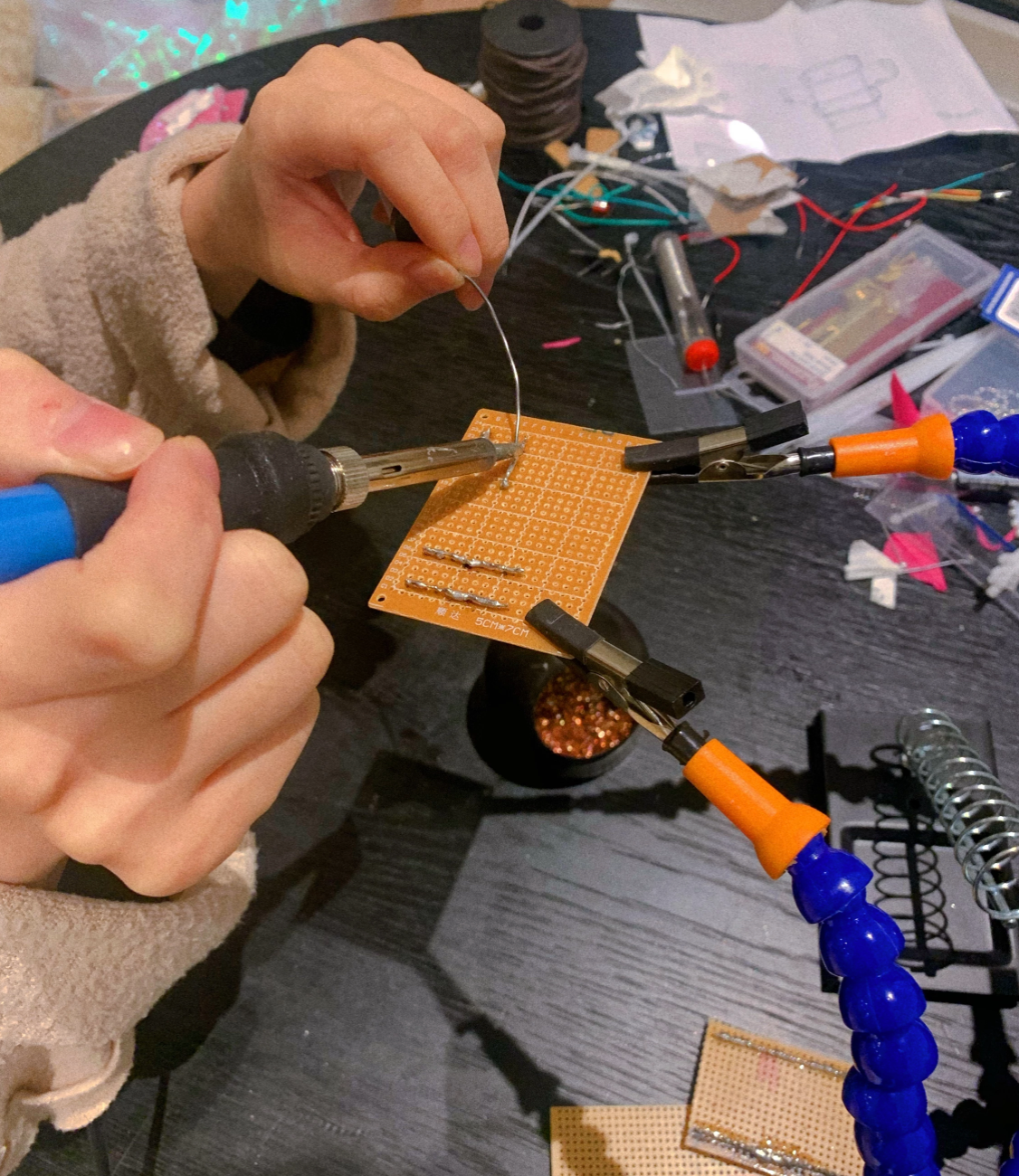
PART 2: Coding, Soldering and Playing:
After testing different sensors and components, we started to build real products.
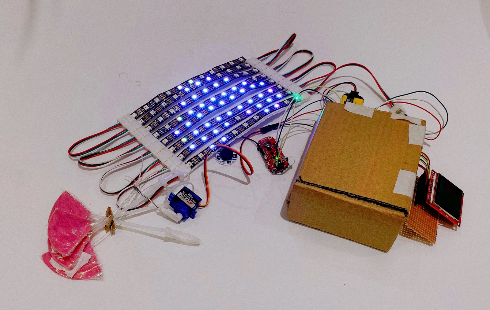
1.LED Strips Mask 🚥

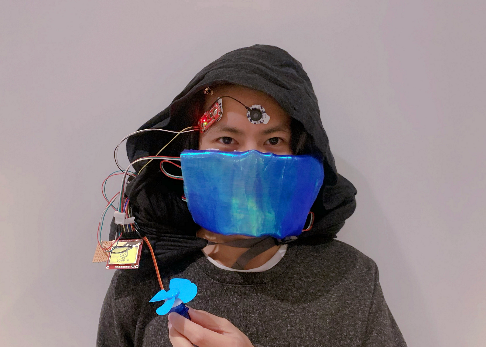
The appearance of the product consists of 8 strips of 11 RGB LED strips. We have selected different types of fabrics for their housing. Cotton is the main fabric, and the laser fabric is the decorative fabric. We designed different patterns according to the needs of users in different scenarios. For example, a smile can express daily greetings, love can express likes, question marks can express confusion and an exclamation point can express excitement. We use the Bluetooth HM-10 module and iPhone. The phone is used as an output device, to communicate and control the display of LEDs, also, as an input device, to display text messages in the screen returned by the Bluetooth.
🤯Difficulty: The sequence of the RGB light does not correspond to the expression used by the library. We need to manually test each light bulb. For example, we want to light the 68th light, pixels.setColor(68, R,G,B), but the 69th light which is no setting will also light up a strange color.
Learn more about referens:
how-to-make-leds-diy-face-mask-using-led-strip-arduino-nano
coding example:
https://github.com/DKARDU/newfacemask/blob/main/gif_led.ino
2.Control the Servo by EMG Sensor
We have made a mechanical flower that is opened and closed by the control of the servo, which is driven by the muscle sensor to sense muscle changes. We hope that when the user smiles, there will be a corresponding external display. The blossoming action is beautiful and can convey friendliness and represent hope.
Material: We first used corrugated cardboard as the petal material, but its fatigue resistance is low. Then, we chose PVC plastic and packaged them with colored paper and laser fabric. For the flower stem material, we first used Dupont thread for testing, but its deflection was large, and it was difficult to restore. So we chose thin plastic strips, which is better than the former in rebound effects.
Assembly: We used a welded cross perforated alloy plate as a fixed cable component, and four nylon wires pull the petals.
Debugging: We set the best rotation angle of the servo and fix the relative position of the mechanical flower and servo.We programmed for loop to control the pulling force time, which makes the movement process more visualized.It is important to set the threshold for the servo.
🤯Difficulty: Material selection is demanding, requiring constant trial and error. Since each part is designed and assembled separately, the mechanical energy loss is large, resulting in poor structural integrity, so the result is not that ideal.

Ideal petal structure

Combination of petal fabric
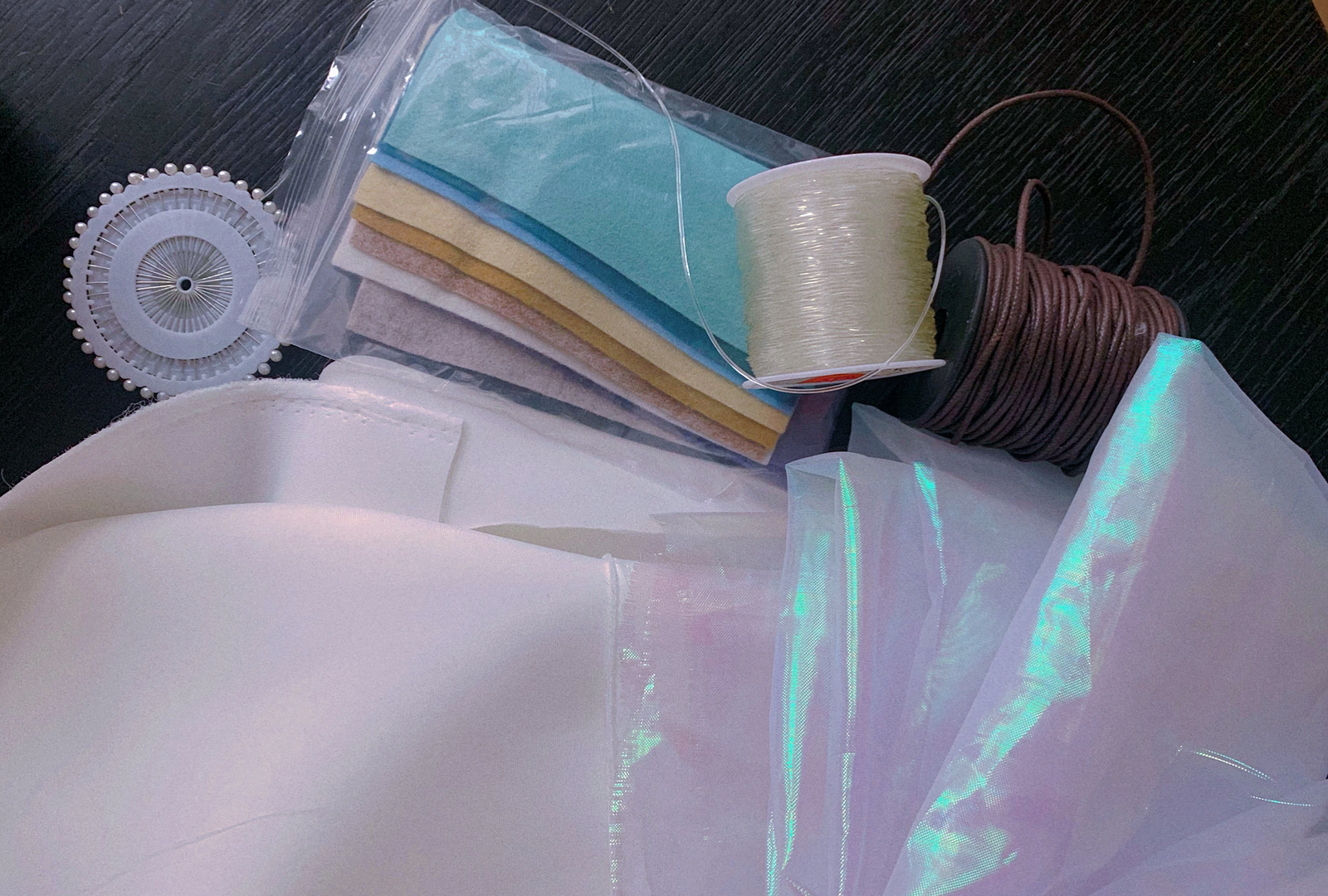
Mask surface material
3.Nokia 5110 LCD Animation 📺
We connect an 84x48 LCD screen, which can be written animation. The .bmp format image data is transformed into arrays that can be read by Arduino. We design 20 illustrations and achieve funny animation by controlling frame and delay time.
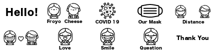
Cute scripts by Yi Dai
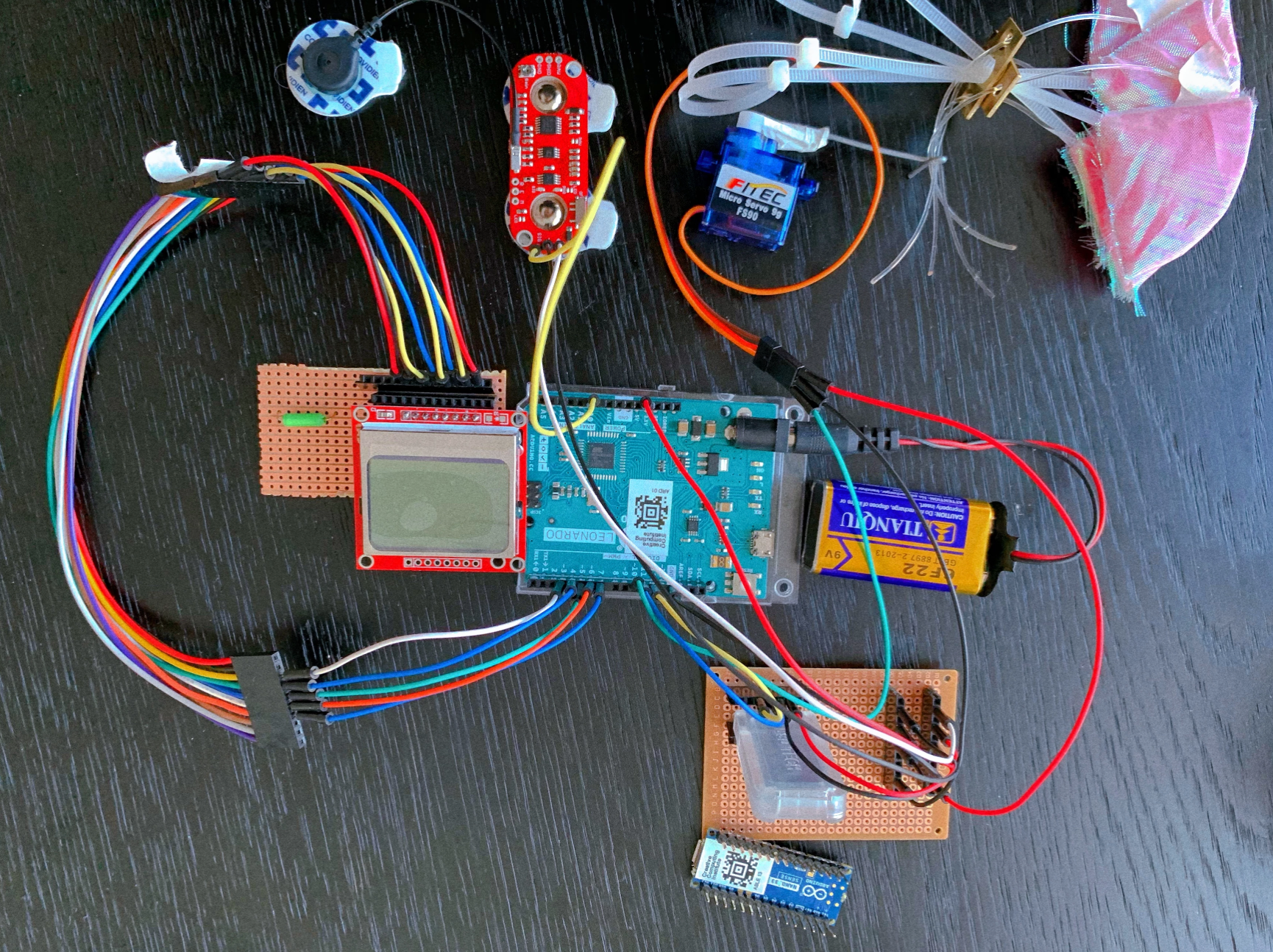
4.Circuit Diagram and Soldering 📺
🖊Simply mark our circuit interface.

🖱Drawn by EAGLE:
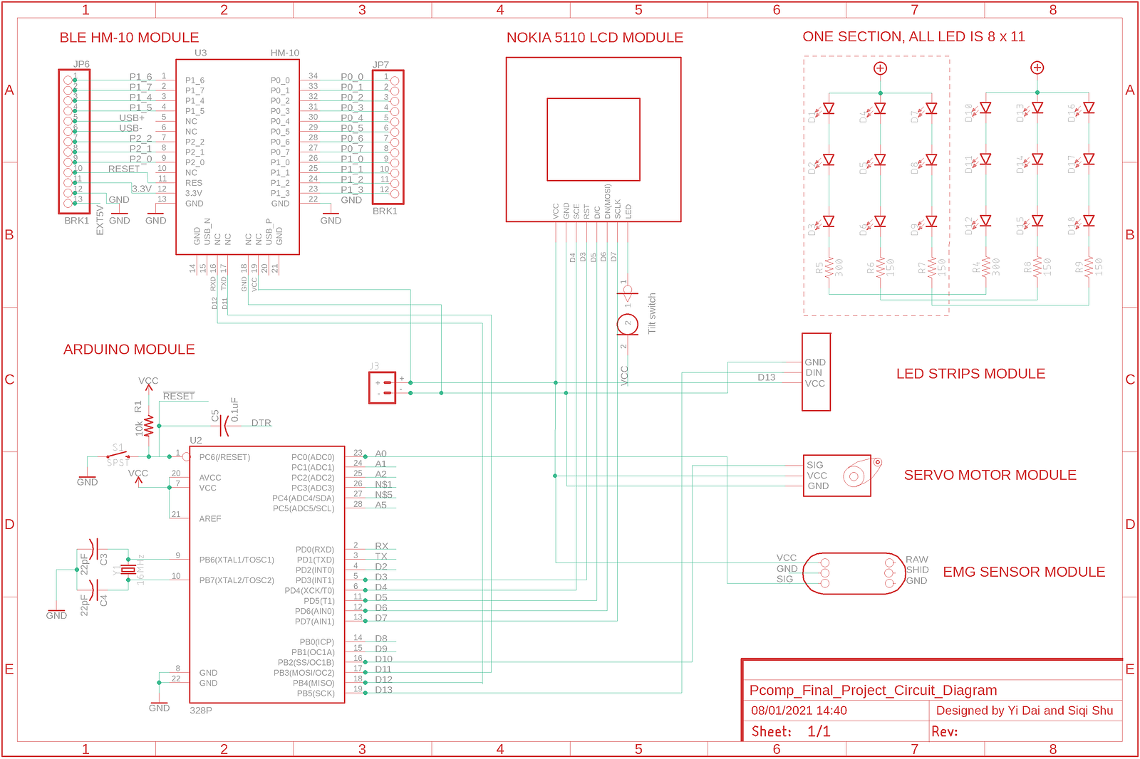
🧩Connect them and solder them together!
5.Final Results 💎

💡About housing:
To place the Arduino board and the soldering board, we first made a 1086 box, but its volume is large, and it is inconvenient to fix it. We have to explore a new shape. We chose a U-shaped pillow, which users can hang around their necks. It is convenient and comfortable.
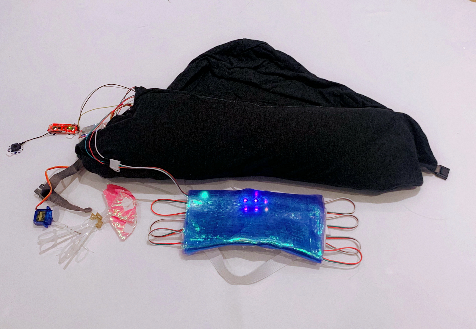
Combined with the U-shaped pillow, it makes wearing more comfortable and looks more natural.
🎈Our final repository:
https://github.com/ShuSQ/CCI_Pcomp_FP_coding
6.Future possibilities for this project
- Continue to improve the components and operation of the mechanical flower.
- Find a better appearance for the mask and a way to fit the face.
- Look for more flexible LED control methods and achieve a variety of dynamic effects,
- Simplify the circuit, reduce the number and size of mounted components, make the device lighter and more comfortable to carry.
- Consider adding a small fan (through the servo rotating), and establishing a ventilation system inside the mask, to solve the problem of poor breathing when the mask is worn for a long time.
~
Else
Finally, I still want to thank my partner Yi Dai. She has made great contributions to the project and can always inspire new ideas. She is responsible and hardworking. She is a very ideal partner and impressive. Thanks again.
About this Post
This post is written by Siqi Shu, licensed under CC BY-NC 4.0.